Modeling Actuation System Architectures with Modelon Hydraulics Library
This blog is Part 1 of a blog series that will demonstrate how the Modelon Hydraulics Library is well suited to the model-based development of an Aircraft Hydraulic Actuation System (AHAS). In this series, of the actuation system development workflow will be covered.
Part 1, below, will focus on the architectural modeling of AHAS. In the upcoming posts we will cover component detailed design, component integration with datasheet-based parametrization and performance assessment of the entire integrated system.
Introduction
The actuation system of an aircraft performs a safety critical function that ensures controllability. Although today’s trend is focused on developing electrical actuation systems, current aircraft and new developments still require hydraulic power to feed the actuators.
AHAS functional breakdown
In this series, the AHAS is defined as the set of actuators that drives the control surfaces and the associated hydraulic systems. An extensive definition should cover the flight control computer (or similar components that perform the same function) in which the actuator control loops are implemented. For simplification purpose, the actuator control loop will be reduced to block diagrams that will still ensure such a functionality. Thus AHAS covers the following main functions:
- Store hydraulic fluid – typically ensured by reservoirs – pressurized or non-pressurized.
- Generate hydraulic power – typically ensured by mechanical pumps, electric pumps, hand pumps, ram air turbine (RAT) and power transfer units (PTU).
- Store hydraulic power – mostly covered by accumulators (also by capacitance effect of the lines).
- Distribute hydraulic power – mostly ensured by rigid lines and hoses as well as dedicated valves to guide the fluid.
- Convert hydraulic power – typically performed by linear or rotary actuators. It can be split into two sub-functions:
- Meter hydraulic power – typically ensured by proportional control valves.
- Transform hydraulic power (in to mechanical power) – usually performed by hydraulic cylinders (linear or rotary).
Architectural modeling of AHAS, using Modelon Hydraulics Library
When developing a system using the Modelica[mfn]All Modelica keywords will be colored in orange in order to highlight them.[/mfn] language, it is convenient to identify the system topology and build a template for this system. The template introduces placeholders – usually called base classes – for the system.
A best practice is to have a placeholder that includes all common parts for the functions that the subsystems must achieve (e.g. interfaces). Note that this is only possible when subsystem boundaries are drawn such that their functions are independent.
All components that are candidates to be template shall extend the base class of the function they fulfill. This enables easy selection of well-suited components by replacing the placeholder by one of the components that extends it, at which point the class will be redeclared accordingly. The same template would then enable building several systems that have the same functional architecture. As a result: 1) models are easily reused between one system to another, 2) model maintenance will be simplified and, 3) the end user can easily configure its system without caring about potential incompatibilities.
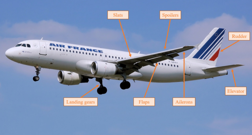
The A320 actuation system includes fifteen control surfaces that are actuated by a total of twenty-one actuators. Except for the actuators that are dedicated to the “direction” control surfaces, all other actuators are using electro-hydraulic servo valves (EHSV) in order to meter the hydraulic power coming from the hydraulic system.
In order to operate safely, in compliance with the dedicated regulations, the A320 includes three independent, segregated and dissimilar hydraulic systems. Each of those is usually named after a color: the green, blue and yellow circuits. Each circuit feeds different actuators that actuate different control surfaces.
This template should be instantiated once per circuit (green, blue and yellow) if the full system should be modeled.
Multiple connections in one connector
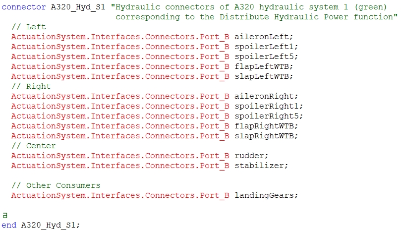
With the proposed architecture, one could wonder how it is possible to model the pressures available at each actuator port of a hydraulic system.
This is made possible with the dedicated hierarchical connectors – which include one connector per actuator (see below), connecting distribute and convert functional models with a single line. Hierarchal connectors also enable the user to connect to each of the internal connectors within a subsystem, making it possible to reach the correct actuator by selecting the correct name.
Conclusion and coming posts
Part 1 has demonstrated how to take advantage of some Modelica key features in order to build the functional model of an AHAS.
In Part 2, 3, & 4, we will detail the actuator models and then illustrate how this architecture model can be used to study AHAS performance in different scenarios.
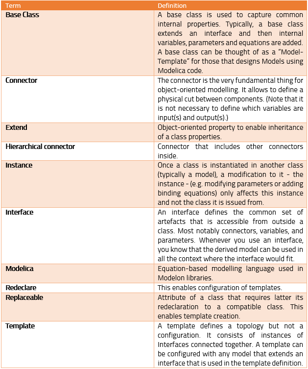
Glossary