Validating Fuel Cell Efficiencies

In the last decade, Polymer Electrolyte Membrane Fuel Cells (PEMFC) have seen an up-tick in popularity and practicality as OEMs and economies work to reach regional and global environmental goals. The automotive industry stands to gain the most from these technologies as PEMFC offer benefits that include:
- low emissions, in comparison to the archaic internal combustion engine
- low operation temperatures (below 80◦C), enabling engines to reach full operation quickly
- lower cost of the materials, in comparison to elevated temperature fuel cells
In order to achieve sustainable commercialization, validating the performance and durability of a rapidly evolving technology and products is needed. A common and precise validation method includes using model-based simulation tools to compare data to performance.
Using Modelon’s Fuel Cell Library , we set out to validate fuel cell efficiencies.
How it works
PEMFC consists of a Membrane Electrode Assembly (MEA), a separator and a collector. Inside the MEA, platinum particles that act as electrode and catalyst are coated. The separator has the gas flow channel at the inner side and in contact with MEA. Gas is supplied into each side of the MEA via gas flow channel to make the following chemical reaction.
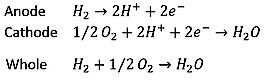
Dry hydrogen and air are provided to the fuel cell via the regulator and the humidifier. The temperature of gas is kept constant by the heater attached to each device. The generated water is exhausted using an exhaust pipe attached to the cathode side.
The theoretical voltage of the PEMFC is 1.23V, at standard conditions. However, due to the losses depicted in Figure. 1, the PEMFC will not operate at such high voltage.
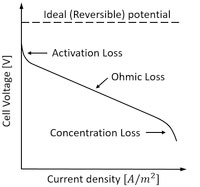
Figure 1. Different losses of the fuel cell
Creating a PEMFC using a Modelon library
The fuel cell membrane model is represented using an object-oriented modeling method that mimics the same configuration of the fuel cell in practical case. See Figure 2, the model was created using templates in Modelon’s Fuel Cell Library.
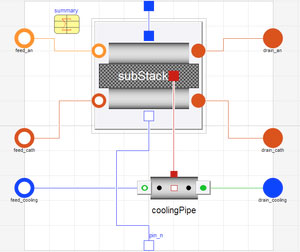
Figure 2. PEMFC model configuration
Voltage is calculated by the following equation to cover the different losses in Figure 1.

Parameterization
Parameterization of the models is as important as the model fidelity itself. It requires effort to match the model and the experiment via a good set of parameters. The following experience is obtained in our work.
- Modification of ohmic loss model – the ohmic loss (Figure 1) of the fuel cell is calculated using the membrane thickness (z) and cell temperature. However, it depends also on many other factors that is difficult to simulate (e.g. bolt fastening torque, surface roughness of parts). It therefore requires to be modified individually by making the comparison with actual value (such as the result from the AC impedance measurement or resistance measurement).
- Setting the limiting (maximum) current density loss JL – The limiting current density JL, at which the fuel is used up at the rate of its maximum supply, has a large effect on the simulation result, but it cannot easily be obtained from the initial condition of the experiment – It needs to be calibrated against the experimental result. Plots of I-V or I-P are generated using FMU (Functional Mock-up Unit) and Excel as FMI. They can be compared with plots of the experimental results in Excel.
FMI based validation
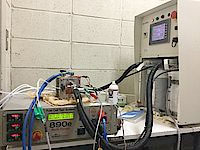
Figure 3. PEMFC Test Bench
To validate the model parameters, the first step is to acquire the measurement of an actual PEMFC. In a recently completed research project, Tokyo Metropolitan University researchers conducted a fuel cell test, as shown in Figure 3. The fuel cell voltage and power are obtained through the experiment.
The parameter validation can be done in many ways. In this case, researchers used Microsoft Excel, to gather measurement data. Simultaneously, the PEMFC test model is exported as a co-simulation FMU with a differential algebraic equation solver embedded. Using Modelon’s FMI Add-in for Excel solution, analyst can import the FMU into the Excel spreadsheet and complete the simulation directly. A further advantage of using FMI technology is that the validation can be continued in a professional simulation environment of choice.
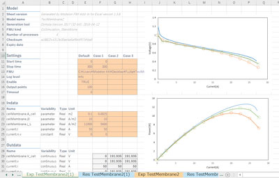
As seen below in the left side of Figure 4, we adjusted the parameters expressing cell geometry and characteristics of MEA. Simulation was successfully done in Excel and the comparison with the measurement data is shown in the right side for the cell voltage-current characteristic and the power-current characteristic.
Next: Researchers will use the validated model for the design optimization of PEMFC. Results will facilitate the development of control scheme for the fuel cell system.
Modelon’s Fuel Cell Library is developed by the first principle that exposes the most important physics nature of the fuel cell. Through the validation work introduced above, it is illustrated that the PEMFC model inside the Fuel Cell Library achieves a good match with the experimental data obtained from the test bed in Tokyo Metropolitan University. The cooperation between Modelon and the university helps researchers to understand the physics behind the measurement data; On the other hand, it confirms the model fidelity of our commercial library.