Designing and developing advanced aircraft escape systems for fighter pilots
Fighter pilots often face critical and life-threatening situations that require a military aircraft manufacturer to design and expertly craft escape systems – ensuring safety opportunities exist in case of emergency evacuation.
In a previous project, Modelon worked with a military aircraft manufacturer on escape systems, specifically the pilot ejector seat, that would propel a pilot’s seat out of an aircraft using a rocket motor. Because the safety and survival of the pilot depends on this system efficiency, proper designing of it is essential. The ejection system must work reliably despite many disturbances such as: aircraft and seat aerodynamics (including their interactions), potential collisions due to continuous movement, uncertainty in body position and mass, and many more.
The new design process uses a model-based approach, delivering critical data needed for the design requirements, and when exchanging information with subcomponent suppliers (for example, on system timing), Additionally, the aircraft manufacturer wanted to shorten the simulation and model validation phase. A focus of the effort was the modeling of the ejector seat propulsion system such as capturing pressure wave propagation, temperature rise and thrust generated due to the combustion of the propellant. This knowledge is of immense importance when designing the systems against material failure and sizing the different system components.
Modelon created pyrotechnical models of the ejector systems using its Pneumatics Library, Modelon Base Library, and custom-built models. The seat propulsion system includes four main components including:
- Cartridge– Used as a starter motor manually ignited by the pilot. Models the combustion of the solid propellant producing heat and pressure used to ignite the engine.
- Hose– This is the connection between the cartridge and the rocket. Models the pressure waves, temperature and enthalpy due to the rapid combustion in the cartridge.
- Engine– Models the multi-body behavior of the engine as well as the combustion of the solid propellant. Through the nozzle, the combustion will generate thrust which ejects the seat.
- Nozzle– Models the generated thrust from the rocket engine given the pressure difference between the chamber and ambient, and inlet and outlet as well as throat areas.
An example layout of the ejector system can be seen in figure 1 below.
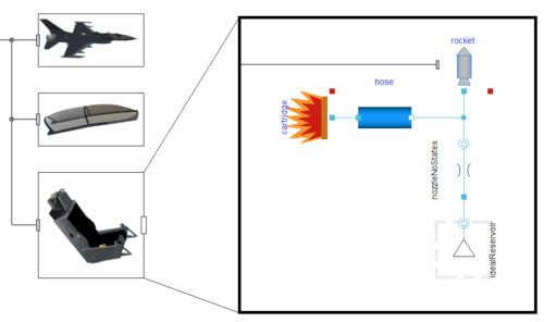
Figure 1: Example layout of the ejector system
Due to different model fidelity requirements and the unavailability of detailed data during early design stages, two variants of the models where created. The first version represents the behavior of the system without a detailed description of its physical implementation. The second version includes more sophisticated equations describing the detailed combustion and propagation physics.
By attaching the rocket to an external seat via the multi body connector a full ejection sequence can be modeled. The ignition time for the cartridge is set to 7.1 second. The pressure and temperature of the rocket engine chamber and cartridge can be seen in figure 2 and 3.
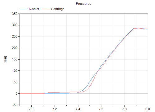
Figure 2: Pressure in rocket and cartridge
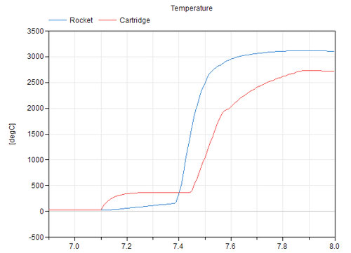
Figure 3: Temperature in rocket and cartridge
The results show that both the pressure and temperature are delayed due to the hose between the cartridge and rocket. At about 7.4 seconds, the temperature in the rocket has reached the ignition temperature of the propellent. This results in a drastic increase of temperature as seen in figure 3. Due to the combustion in the rocket, thrust is generated and the seat is launched. Figure 4 show the vertical acceleration of the seat in g’s due to the generated thrust.
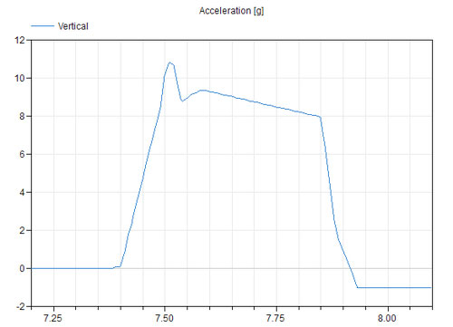
Figure 4: Vertical acceleration of seat
The peak acceleration is around 11g and the propellent is burned out in about 0.5 seconds. In this example, two phases of the ejection are modeled. The first part is the launch phase where the seat accelerates to its peak acceleration. Then a short period of deceleration before the sustainer phase starts at approximately 7.5 seconds.
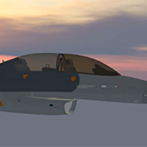
Below you can see a video visualizing the vertical launch of the seat from an aircraft.This video was generated via the Visualization Library developed by DLR, the German Aerospace Centre (http://www.systemcontrolinnovationlab.de/methoden-tools-2/modellbibliotheken/).
The aircraft manufacturer has deployed the design process and leveraged the results in a new aircraft program. The aircraft manufacturer now has higher confidence in the reliability of its methods and models, and uses model-based design with its suppliers. Shortened modeling and validation cycles give it a competitive advantage.